Introduction
Download
Hyunsuk Ko, Han Suk Shim, Ouk Choi and C.-C. Jay Kuo. MCL-SS: “Robust uncalibrated stereo rectification with constrained geometric distortions (USR-CGD).” in Image and Vision Computing, vol. 60, pp. 98-114. 2017. PDF
Download link (Google Drive): LINK
Download link (Hugging Face): LINK
Contact Info: Hyunsuk Ko (kosu9980@gmail.com)
Database Description
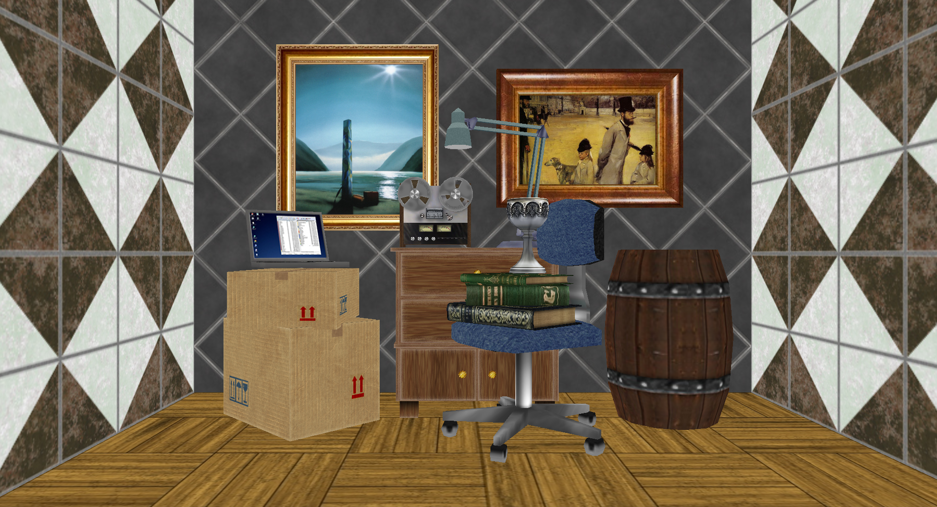
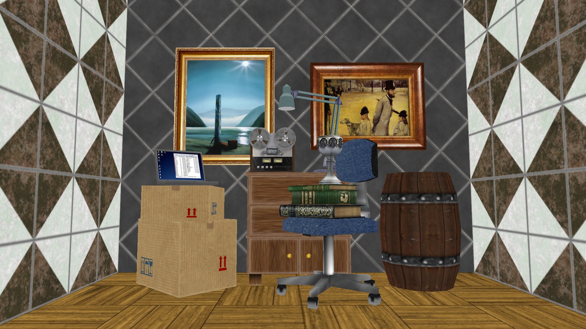
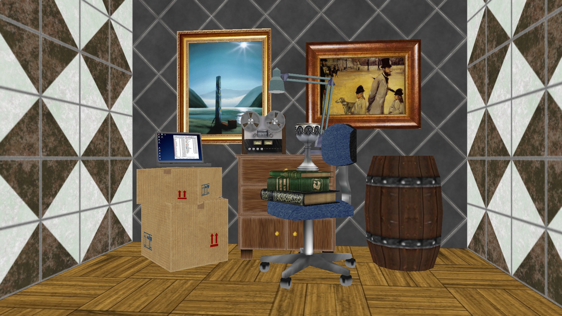
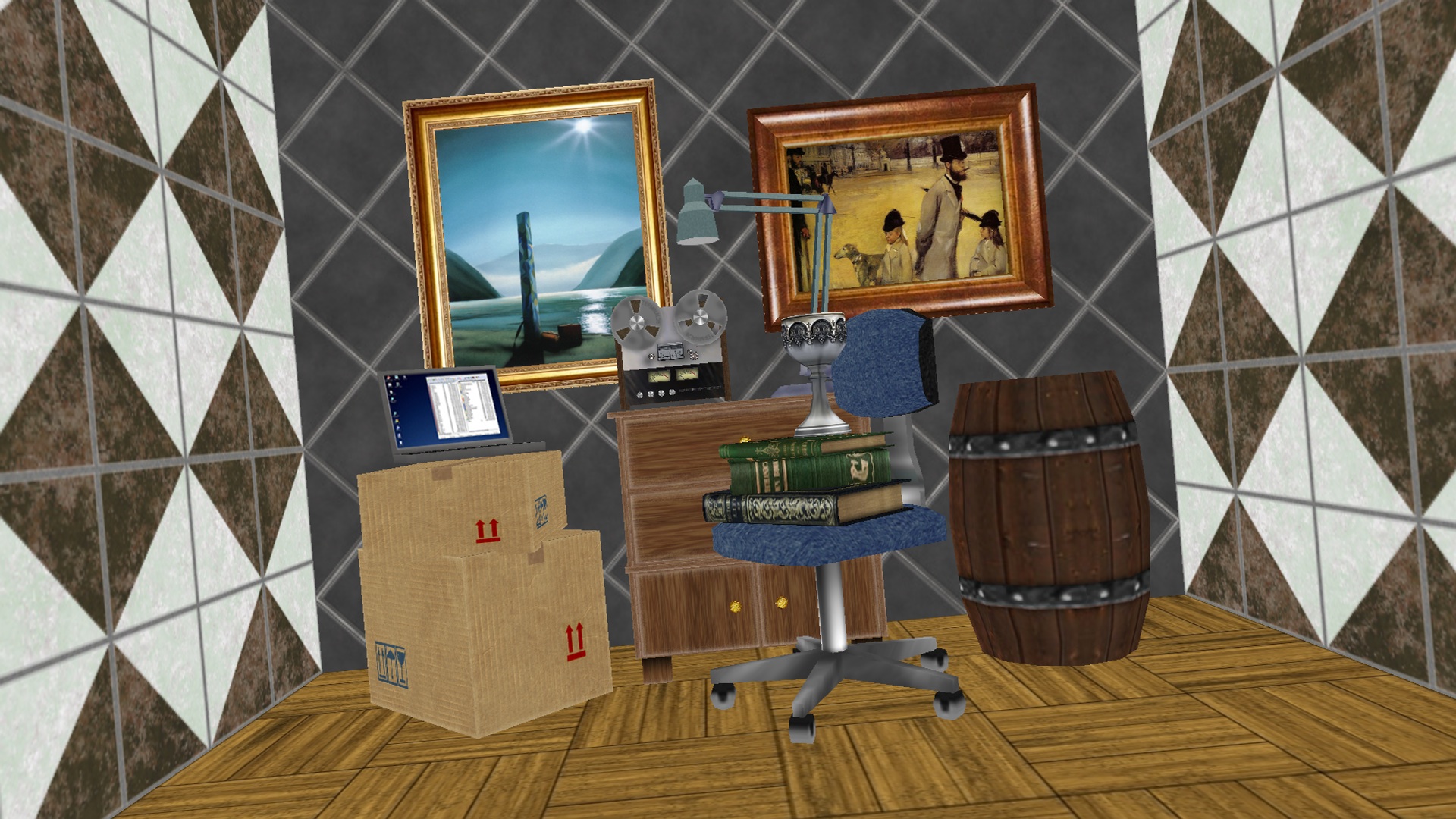
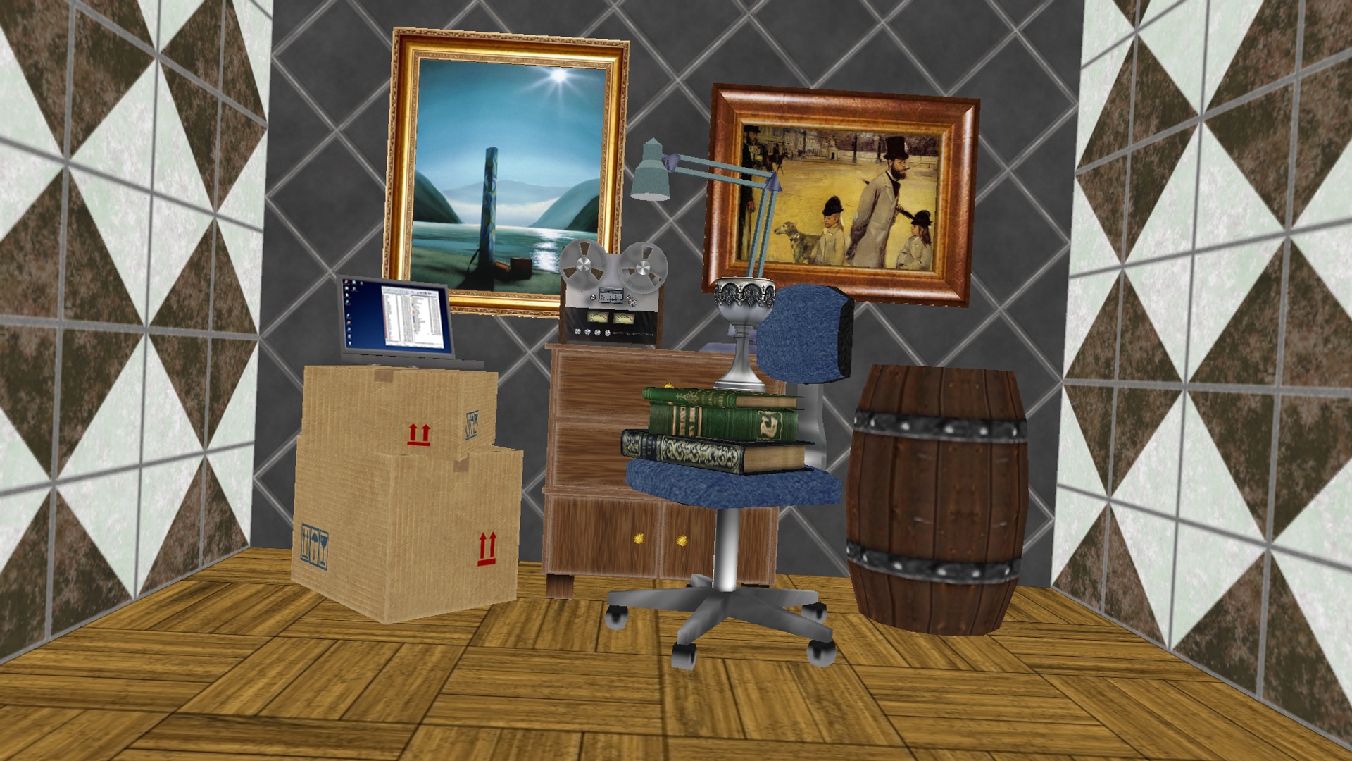
MCL-SS consists of four synthetic stereo image pairs generated by OpenGL programming, which are shown in Fig. 1. The advantage of using a synthetic image is that several geometric distortions can be easily applied to left and right images.
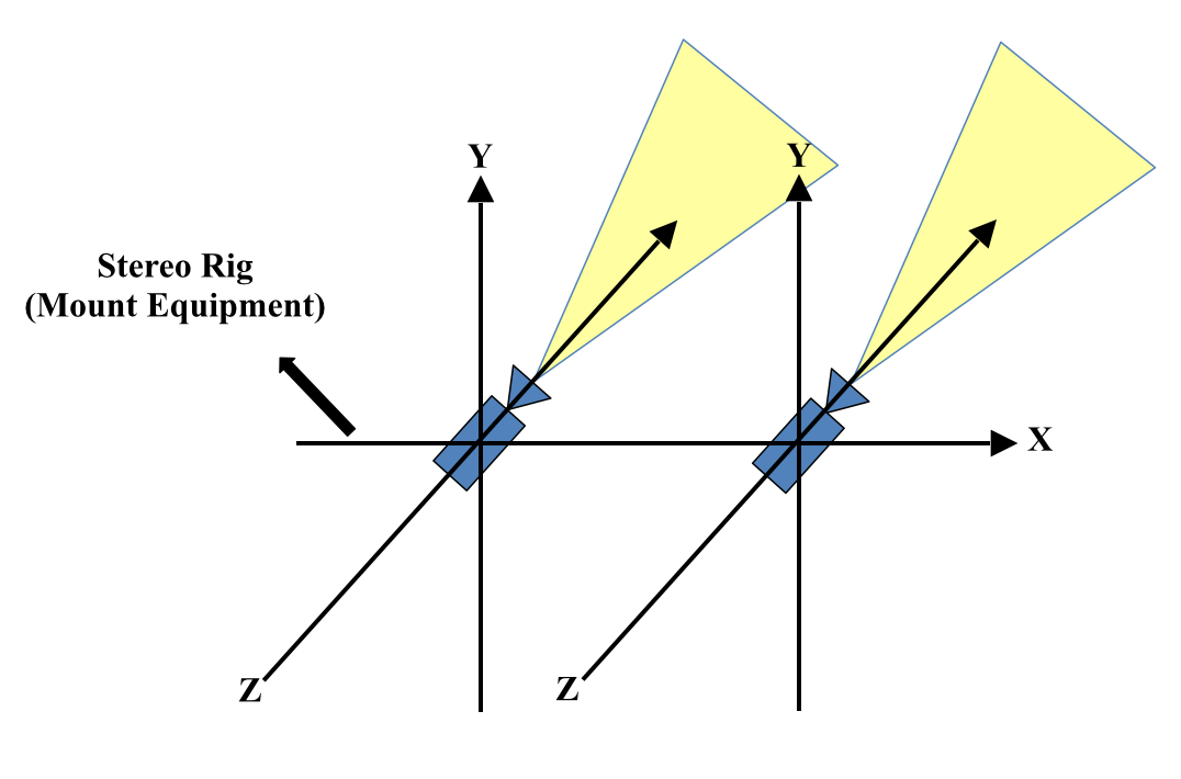
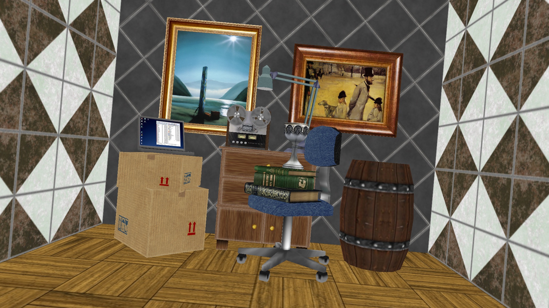
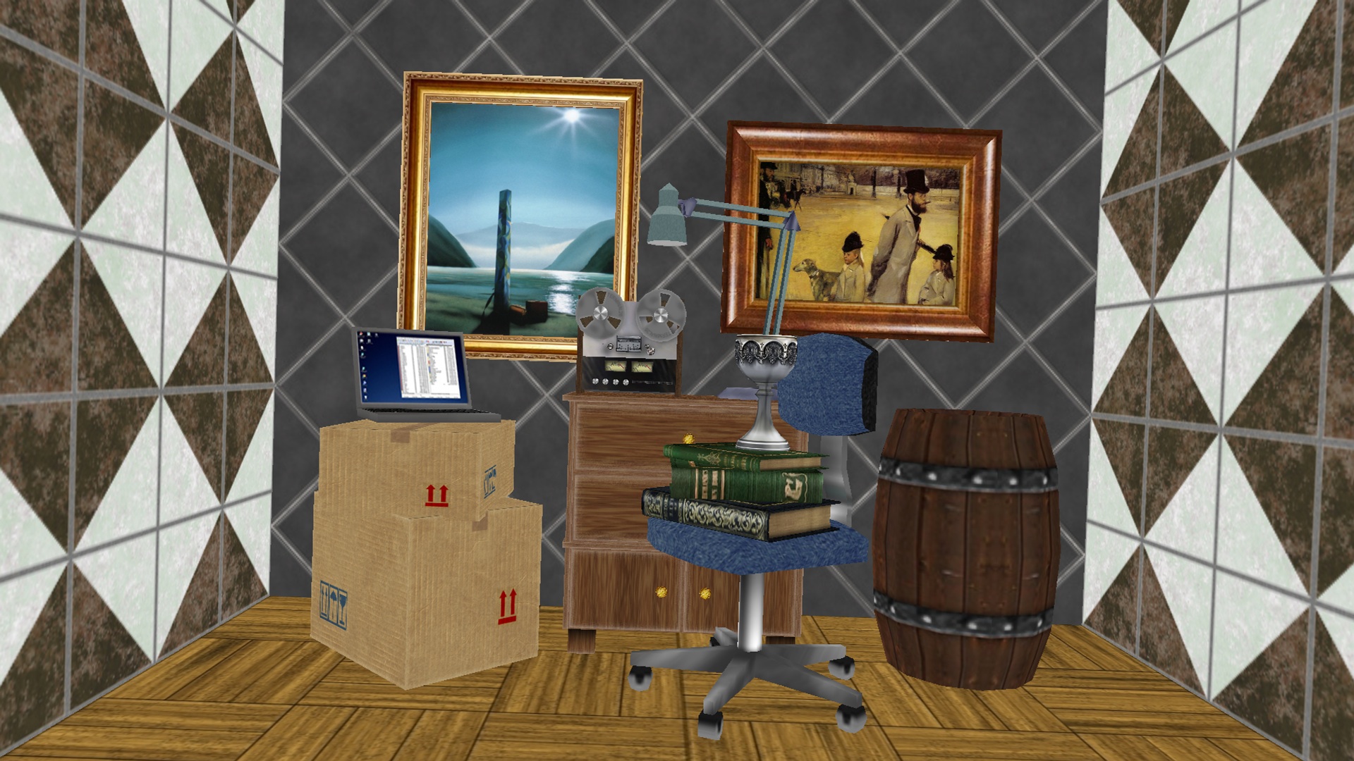
Assuming that two cameras are initially set as shown in Fig. 2, we can translate or rotate each of cameras along X-/Y-/Z-axes. This allows us to mimic some real camera configurations. For example, for the rotational geometric distortion, we can emulate converged camera setup by rotating two cameras on Y-axis in the opposite direction. For the translational distortion, we can also imitate wide baseline, vertical misalignment, and different zoom levels by moving two cameras on X-/Y-/Z-axes, respectively. Also, we can apply all the six distortions together.
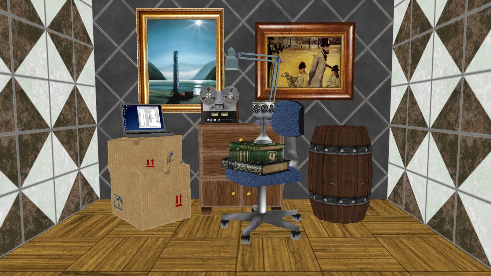
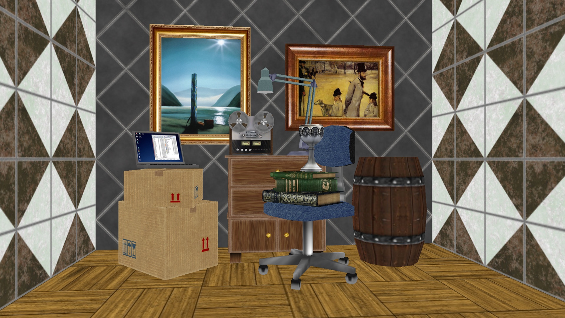
For each of original synthetic stereo image pairs, we generate eight test stereo pairs, where six of them are obtained by applying single geometric distortion while the other two are generated by applying all the six geometric distortions together. As an example, a set of test images with different geometric distortion is demonstrated in Fig. 3~Fig. 5. Concretely, we move left and right cameras along X & Y axes and the range of increased disparity is 0~185 pixels. The ratio of object’s sizes between left and right images due to the cameras’ translation on Z-axis is about 11.98%~31.24%. Finally, the angle difference due to the camera rotation is 10˚on each axis.
Acknowledgement
Copyright Notice
Permission is hereby granted, free of charge, to any person obtaining a copy of the database and associated documentation files (the “MCL-SS DATABASE”), to deal in the database without restriction, including without limitation the rights to use, copy, modify, merge, publish, distribute, and/or sell copies of the MCL-SS DATABASE, and to permit persons to whom the is furnished to do so, provided that the above copyright notice(s) and this paragraph and the following two paragraphs appear in all copies of the MCL-SS DATABASE and in supporting documentation.
IN NO EVENT SHALL THE UNIVERSITY OF SOUTHERN CALIFORNIA BE LIABLE TO ANY PARTY FOR DIRECT, INDIRECT, SPECIAL, INCIDENTAL, OR CONSEQUENTIAL DAMAGES, INCLUDING LOST PROFITS, ARISING OUT OF THE USE OF THE MCL-V DATABASE, EVEN IF THE UNIVERSITY OF SOUTHERN CALIFORNIA HAS BEEN ADVISED OF THE POSSIBILITY OF SUCH DAMAGE.
THE UNIVERSITY OF SOUTHERN CALIFORNIA SPECIFICALLY DISCLAIMS ANY WARRANTIES, INCLUDING, BUT NOT LIMITED TO, THE IMPLIED WARRANTIES OF MERCHANTABILITY, FITNESS FOR A PARTICULAR PURPOSE OR NON-INFRINGEMENT. THE MCL-V DATABASE PROVIDED HEREUNDER IS ON AN “AS IS” BASIS, AND THE UNIVERSITY OF SOUTHERN CALIFORNIA HAS NO OBLIGATIONS TO PROVIDE MAINTENANCE, SUPPORT, UPDATES, ENHANCEMENTS, OR MODIFICATIONS.
Left Images
Right Images
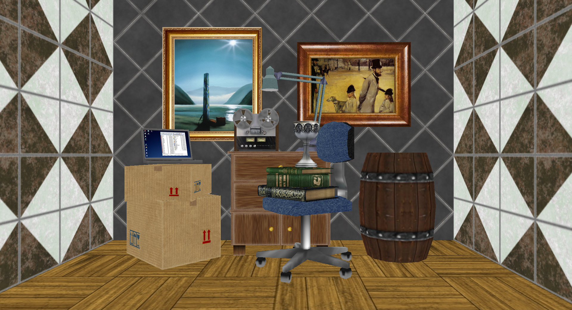
Interior
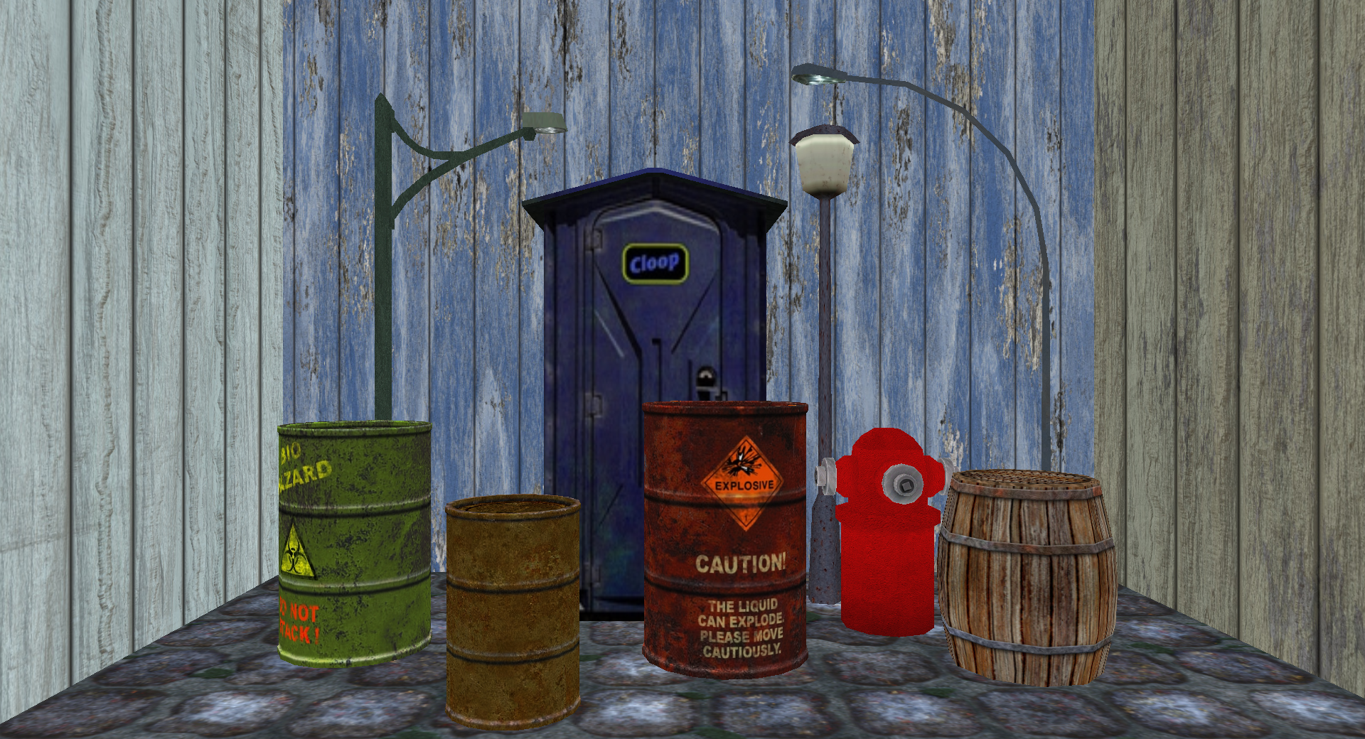
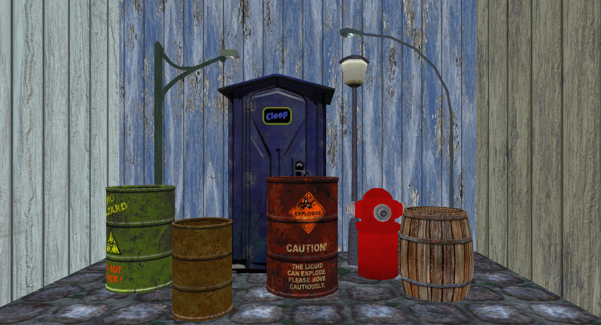
Street
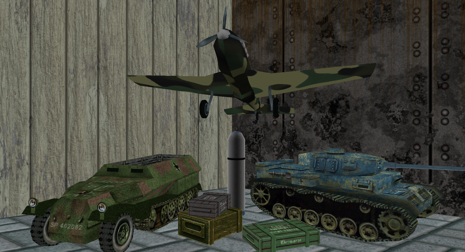
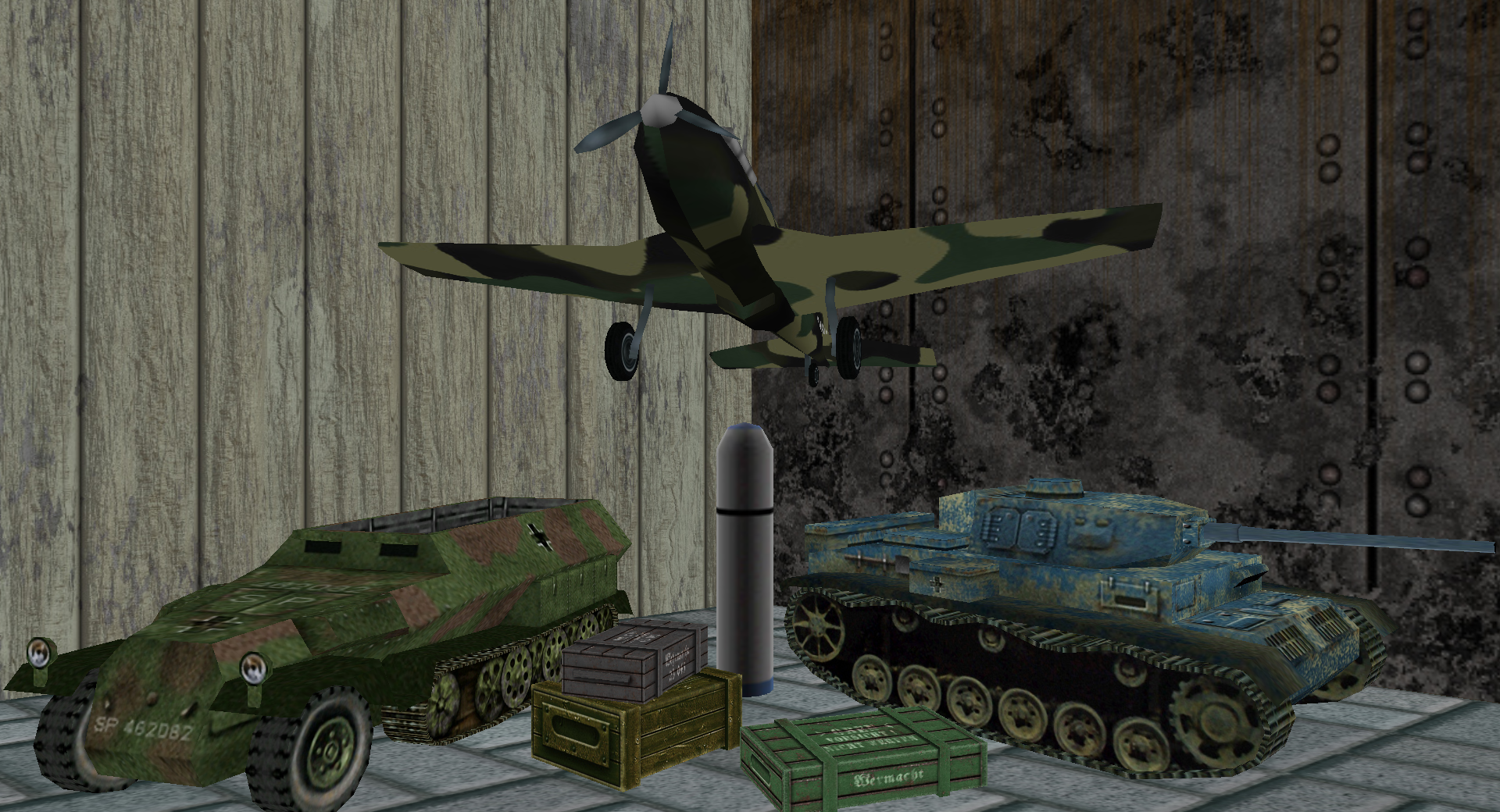
Military
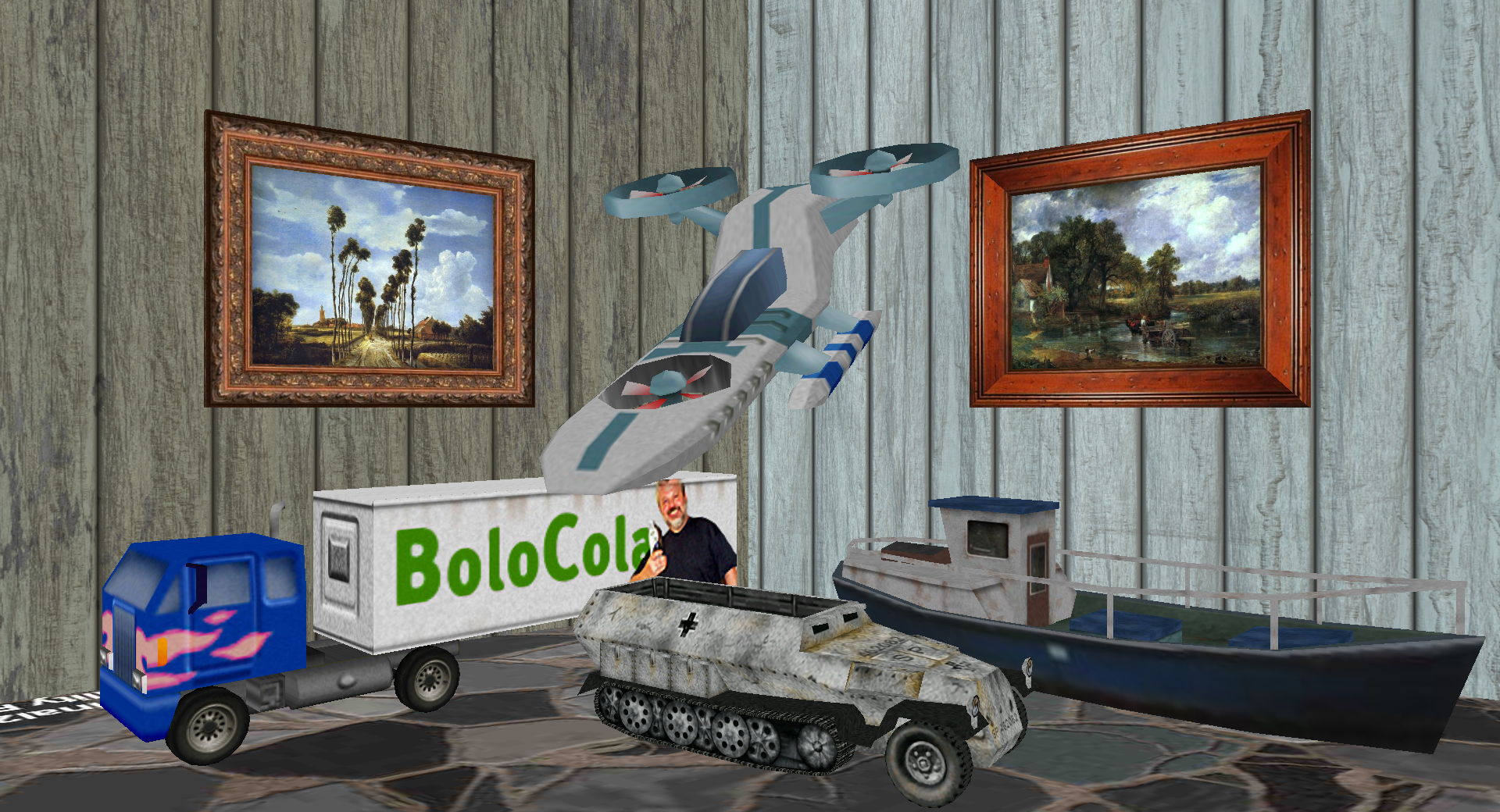
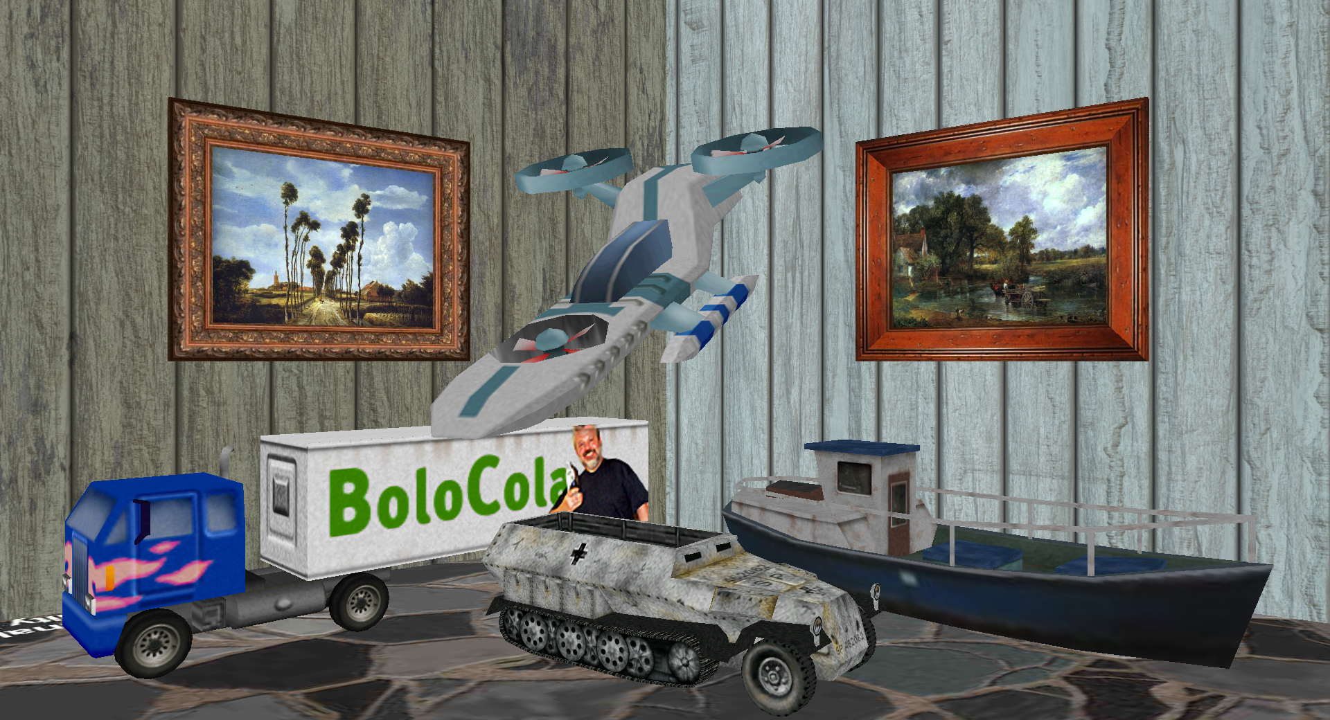
Vehicle
Fig. 1 Four reference image pairs
Left Image
Right Image
(a) X-axis
(b) Y-axis
(c) Z-axis
Fig. 3 Rotation Distortion
Left Image
Right Image
(a) X-axis
(b) Y-axis
(c) Z-axis
Fig. 4 Translation Distortion
Left Image
Right Image
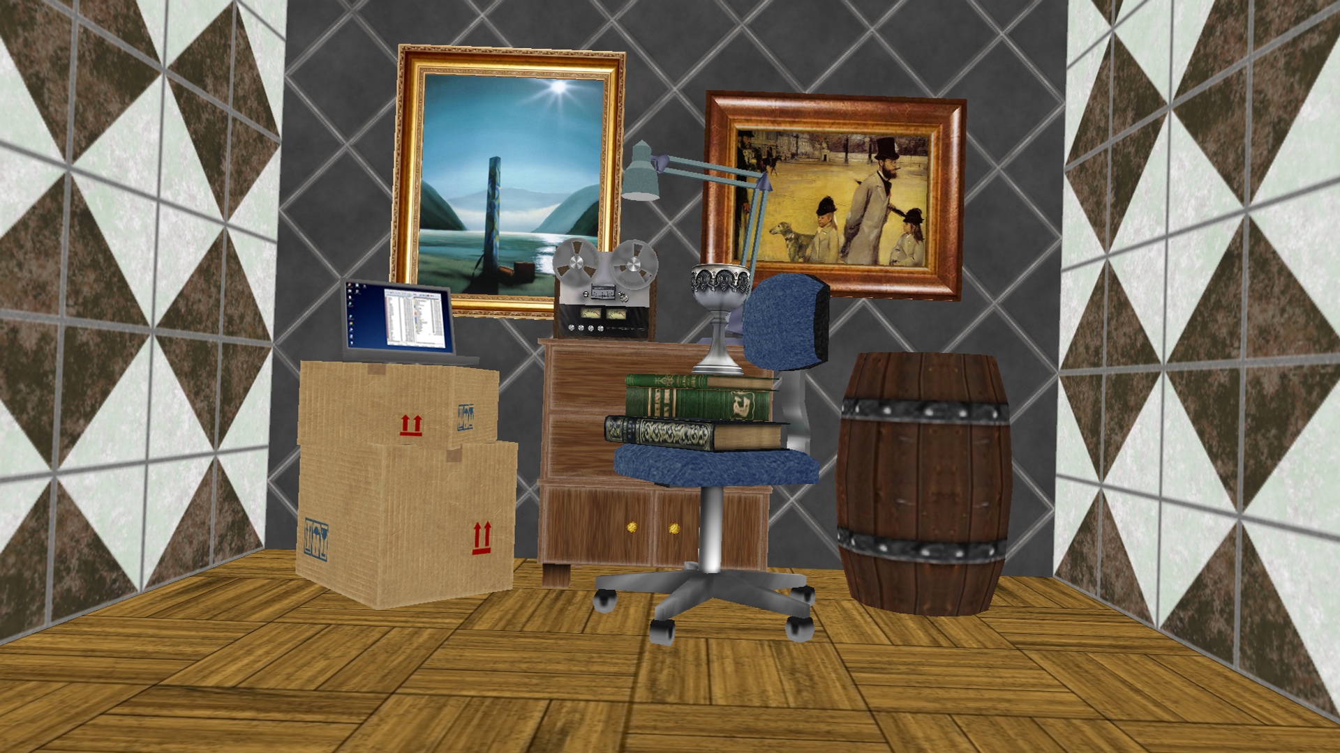
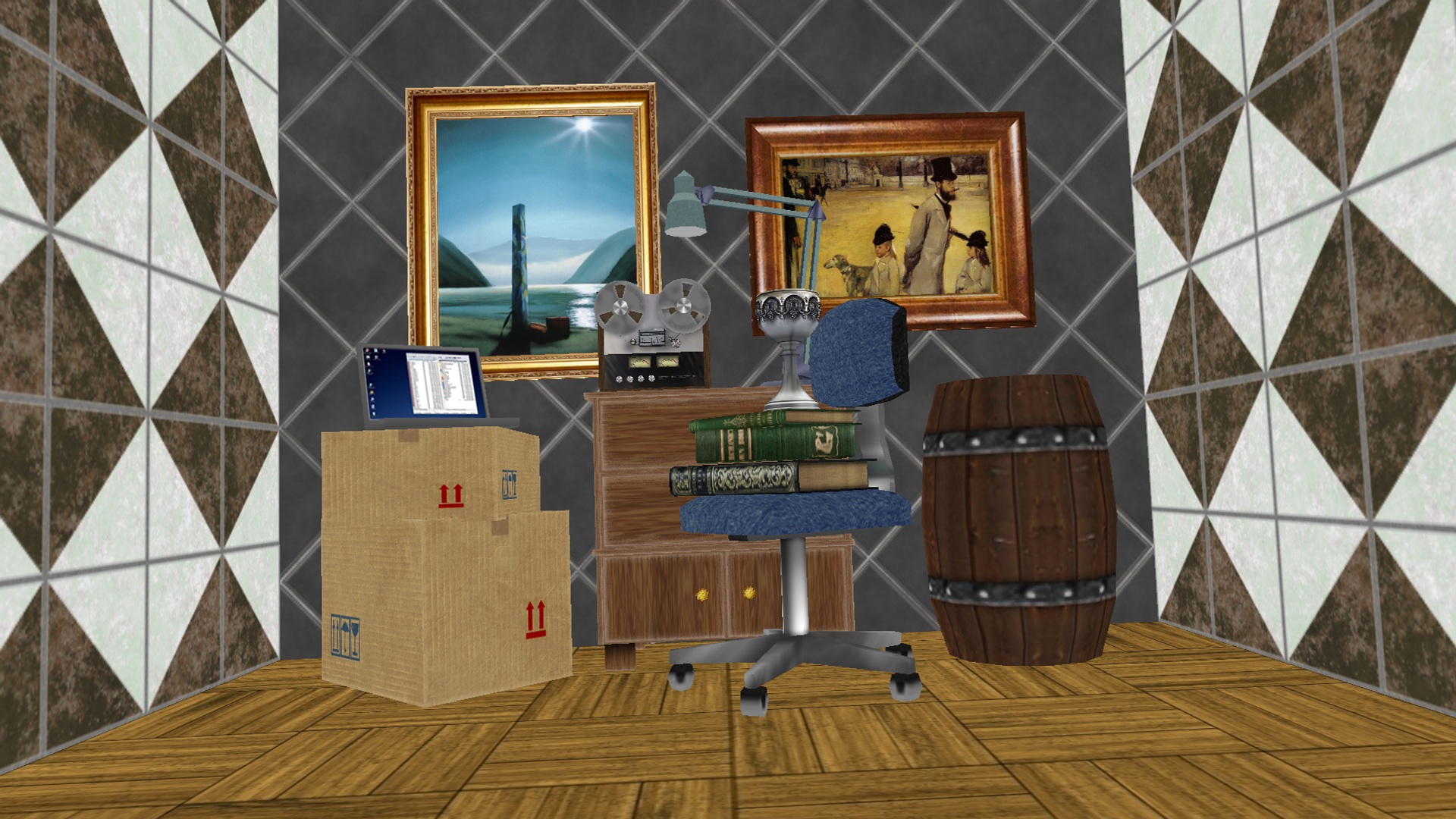
Fig. 5 Compound Distortion